

Photocatalysis: Mechanism, Materials and Measurement
Photocatalysis speeds up a chemical reaction through light in the presence of a semiconductor that is not itself consumed. Ultraviolet or visible photons of sufficient energy generate electron-hole pairs in the photocatalyst – most commonly titanium dioxide (TiO2), zinc oxide (ZnO) or, increasingly, visible-light-active materials such as carbon nitride (g-C3N4) – which form reactive oxygen species at the surface and break down organic pollutants, microorganisms or dissolved water constituents. The technical goal is reproducible, energy-efficient photocatalytic activity for air purification, water treatment, self-cleaning surfaces or photocatalytic hydrogen production. What decides the outcome is not the electrical rating of the lamp, but the spectral irradiance that actually reaches the catalyst – photon flux follows from it, and only from photon flux can photonic efficiency and quantum yield be calculated.
How is the market for photocatalysis developing?
There is no single, clearly bounded market statistic for “photocatalysis” – commercial studies scope photocatalysts, photocatalytic equipment and photocatalytic coatings very differently. The market for photocatalysts themselves is well documented: it is estimated at roughly 3.2 to 3.3 billion US dollars for 2026, with an annual growth rate of 8.7 to 8.9 percent through 2033 (Mordor Intelligence, 2026; Persistence Market Research, 2026). Titanium dioxide accounts for around 78 percent of material revenue, and the Asia-Pacific region – with roughly 44 percent revenue share and about 9.4 percent growth – is the fastest-growing (Persistence Market Research, 2026).
Adjacent, clearly bounded sub-markets show the same dynamics from a different angle: the market for self-cleaning coatings stood at about 4.4 billion US dollars in 2024 and is expected to reach 6.7 to 8.7 billion US dollars by 2032 to 2034, corresponding to 5.4 to 7.1 percent annual growth (Databridge Market Research, 2025; Market.us, 2025). Photocatalytic air purification and photocatalytic water treatment are put at anywhere from a few hundred million to over ten billion US dollars depending on scope (Intelmarketresearch, 2024) – the wide range mostly reflects whether raw material, equipment or complete installations are being counted.
The underlying driver is technically unambiguous: growth is driven mainly by regulation-driven demand for indoor air quality, by building codes for self-cleaning and air-purifying façade and paving materials, and by expanding water treatment for persistent organic pollutants. This growth shifts value from plain material sales to tested, certified systems – photocatalytic performance has to be demonstrated to a standard, not merely claimed. That applies across all three product-facing value stages – raw materials and powders, coatings and building products, and equipment – while in research (hydrogen production, CO2 reduction) it is the photon-based quantum yield that decides whether a new material is genuinely an advance. Standardised test methods and measurement technology that captures photon flux and irradiance at the site of the photocatalytic reaction, rather than at the lamp, therefore matter more directly than before.
Four developments determine where photocatalysis is heading technically:
- Shift from mercury lamps to UV-A LED arrays in test and production equipment. Technical consequence: the spectrum moves from a broad line/continuum spectrum to a narrow band; older AQY values determined with mercury lamps are not transferable to LED-based test setups without renewed characterisation.
- Development of visible-light-active photocatalysts. Doped TiO2 variants, g-C3N4 heterojunctions and Z-scheme systems shift usable excitation into the visible range. Technical consequence: UV-only radiometers become insufficient for full characterisation; spectral measurements spanning the UV and visible ranges, and solar-simulated test conditions, gain in importance.
- Advancing standardisation. Updates to ISO 10678 and supplementary test methods such as EN 16845-1 improve the comparability of published photocatalytic activity values. Technical consequence: comparability only results if the method for determining photon flux is documented alongside it.
- Research into photocatalytic hydrogen production and solar fuels. Newer oxyhalide-based and heterostructured photocatalysts reach increasing quantum yields at lab scale. Technical consequence: moving from lab to pilot scale requires renewed optical characterisation, because path length and self-shading change.
How does photocatalysis work?
Photocatalysis at semiconductors rests on exciting electrons across the band gap. When a photon is absorbed with energy at least equal to the band gap energy E_g, an electron is lifted from the valence band into the conduction band, leaving a positively charged “hole” (h⁺) behind. This electron-hole pair either recombines without radiation – in which case the excitation is lost without chemical effect – or migrates to the surface and triggers redox reactions there: the hole oxidises water or hydroxide ions to hydroxyl radicals (•OH), one of the most reactive oxidants in aqueous systems, while the electron reduces adsorbed oxygen to superoxide radical anions (O2•⁻). Both radicals, along with the directly oxidising hole, break down organic molecules, microorganisms and inorganic pollutants. The rate of this process is set by the competition between charge separation and recombination, which in turn depends on crystal structure, defect density, doping, surface state and – in heterojunctions – on the band alignment between two semiconductors.
Which materials and light sources are used for photocatalysis?
Photocatalysis is not a self-contained industry but a cross-cutting technology spanning materials science, environmental engineering and energy technology. Titanium dioxide still dominates because it is chemically stable, non-toxic and inexpensive; its three natural crystal phases – anatase, rutile and brookite – have different band gaps and therefore different activation wavelengths. Zinc oxide sits at a similar spectral position but shows lower long-term stability under humid or acidic conditions. For excitation in the visible range, carbon nitride (g-C3N4), nitrogen- or carbon-doped TiO2, plasmonic co-catalysts and Z-scheme heterojunctions are gaining ground because they improve charge separation and shift absorption into the visible spectrum.
Five types of light source are used for testing and processing, differing markedly in spectral purity and application range. Low-pressure mercury lamps (“blacklight” tubes) provide an established line spectrum at 365 nm but age in their line ratio and contain mercury; medium-pressure mercury lamps deliver high UV and visible output together from a broad continuum, at the cost of high thermal load. UV-A LEDs at 365, 385 or 395 nm are narrowband (typically 10 to 15 nm FWHM), mercury-free, fast-switching and give stable dose control – though their emission peak is temperature-dependent, and they do not cover visible-light-active materials. For visible-light-active and solar-driven systems, a xenon solar simulator with an AM1.5 filter serves as a more realistic test source with a continuous spectrum close to sunlight. White-light LEDs and fluorescent tubes are a simple, low-cost test source for indoor applications, but often carry too little UV content for UV-active reference materials.
Which process variables matter?
Photocatalytic performance is not set by any single quantity, but by the interplay of several physical and chemical variables that must be captured separately. The starting point is the spectral irradiance at the catalyst (mW/(cm²·nm)): only the fraction above the band gap energy can generate electron-hole pairs, and the rest does not contribute to the reaction even though it adds to the total radiant power. From this follows the photon flux (mol/(s·m²) or photons/(s·cm²)) – chemical conversion is set by photon counts, not by wattage, and two sources of equal power but different wavelength deliver different photon fluxes. Band gap energy and absorption edge (eV or nm) fix which part of the source spectrum can be used at all; a shift of the absorption edge by only a few tenths of an electronvolt decides whether a material is UV- or visible-light-active. Apparent quantum yield (AQY, dimensionless, usually given as a percentage) describes what share of the incident photons actually triggers a productive event – it is not a material constant but depends on concentration, reactor geometry and light intensity.
Catalyst loading or active surface area (g/L or m²/m²) also determines how much radiation can be absorbed before it leaves the reactor unused – at too high a loading, penetration depth falls and part of the catalyst stays unilluminated. Oxygen content and mass transport (mg/L or mol/(m²·s)) limit the reaction independently of the radiation available, once the usual electron acceptor, oxygen, is not replenished fast enough. In liquids, irradiance falls exponentially with optical path length according to the Beer-Lambert law; scattering from particles or turbidity (NTU) shortens the effectively usable reaction zone further. Temperature, finally, affects adsorption equilibria, reaction kinetics and, in some systems, the recombination rate of the charge carriers.
What limits the process or causes errors?
Electrical lamp power is not an optical process variable. A statement such as “100 W UV lamp” describes neither the usable spectral fraction nor the share that actually reaches the catalyst. What is meaningful is only the spectral irradiance at the reaction site and the photon flux derived from it.
Quantum yield and apparent quantum yield are frequently confused. The “true” quantum yield refers to the number of absorbed photons; in scattering suspensions or opaque layers this value is practically impossible to measure directly. In practice, the apparent quantum yield (AQY) is therefore reported instead, referring to the number of incident photons. Two studies with identical material but different reactor geometry and irradiance can report markedly different AQY values without the material itself differing. It also follows that irradiance measured at the reactor wall or outside the cuvette is an upper bound, not a balance of the photon flux actually available – reflection, absorption, scattering from particles and shading by reactor walls all change the irradiance between the lamp exit and the catalyst surface.
The reciprocity law holds only within limits in photocatalysis: at low irradiance, reaction rate rises roughly in proportion to photon flux, but as irradiance increases, the density of photogenerated charge carriers rises too, so the recombination rate grows disproportionately and the apparent quantum yield falls – doubling the lamp power therefore routinely delivers less than double the reaction rate, and a higher photon flux is not always the simplest fix, since it can also raise the thermal load on the catalyst. A pure time figure is consequently not a transferable process variable either: a degradation time is reproducible only within an unchanged apparatus configuration, and if lamp, distance, reactor geometry or catalyst loading change, the effective photon flux shifts without the stated time revealing it. Crystal phase and crystallinity are frequently underestimated: commercial TiO2 is often a mixed-phase material with differing recombination behaviour between phases, and its photocatalytic activity does not follow additively from the individual phases but depends on the quality of the interface between them.
The instrument adds its own contribution: a sensor calibrated against a different type of source shows an extra error on a narrowband LED. The background is set out under spectral mismatch of UV sensors and selection of UV sensors.
Suspension or immobilised catalyst?
Suspended and immobilised catalysts pose different measurement problems. A suspension offers a large active surface but complicates separation and light transport: as particle concentration rises, penetration depth falls, and a growing share of the radiation is consumed in the layer nearest the window.
Immobilised films on glass, membranes or porous supports are easier to handle and easier to describe optically, because the active area is known. In exchange, smaller active surface and mass transport limit the rate. When the two approaches are compared, irradiance referred to the active area is a sounder basis than any figure referred to reactor volume.
What role do reactor geometry and irradiation uniformity play?
Photocatalytic experiments run in very different geometries: on coated glass, in suspension, on membranes, in flow-through reactors, on porous supports or in microreactors. A reading taken outside the reactor therefore does not automatically describe conditions inside the reaction volume – reflection, absorption, scattering and shading all change what is available.
With flat samples, the uniformity of the irradiation field decides whether every part of the same specimen receives the same dose. In liquids, attenuation along the optical path is added, and it depends on wavelength. Comparative work should therefore record working distance, sample height and – over larger areas – a spatial grid. That is what turns a lamp setting into a reproducible optical boundary condition.
What role does the absorption edge of the material play?
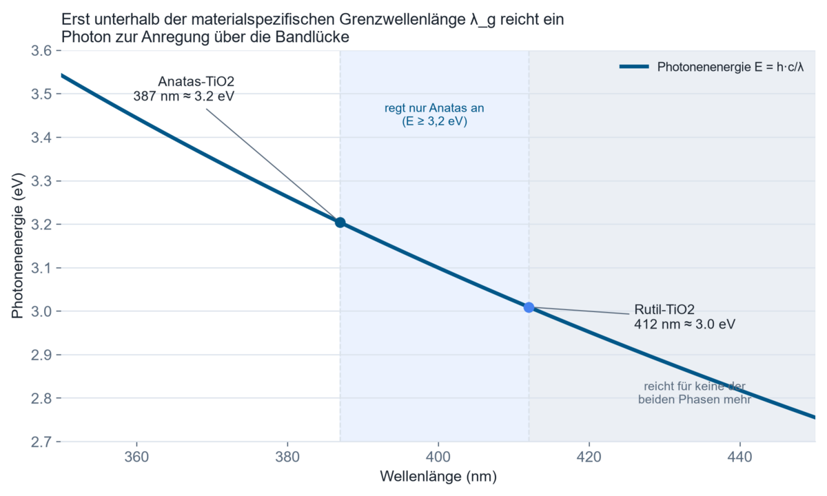
Photocatalysts do not have a sharp threshold wavelength but an absorption edge of finite steepness. Defects, doping and oxygen vacancies create additional intermediate states that allow – usually weak – absorption even below the nominal band gap energy. Commercial TiO2 (such as P25) is an anatase-rutile mixed-phase material with an effective absorption edge around 387 nm; pure anatase and rutile phases differ from that by several nanometres. For visible-light-active materials such as doped TiO2 or g-C3N4, the edge shifts markedly into the visible range, so a UV-only reading no longer captures the usable excitation fully – one reason test sources and measurement equipment for such materials need to cover the UV and visible ranges together.
Expert box: band gap energy, photon flux and quantum yield
Band gap energy. From E_g = h · c / λ_g follows the threshold wavelength λ_g, below which a photon carries enough energy to lift an electron across the band gap. For anatase TiO2 with E_g ≈ 3.2 eV this gives λ_g ≈ 387 nm, for rutile with E_g ≈ 3.0 eV a longer threshold wavelength around 410 to 413 nm. Photons of longer wavelength do not contribute to excitation, regardless of how many there are.
Photon flux. Spectral photon flux follows from the spectral irradiance E(λ) via N_Ph(λ) = E(λ) · λ / (h · c). Only integrating over the spectral range actually absorbed by the material yields the photon flux relevant to the reaction – not the total, broadband-measured irradiance.
Apparent quantum yield (AQY). By the IUPAC definition, quantum yield is the ratio of the number of defined events to the number of absorbed photons; the more commonly used apparent quantum yield instead refers to the number of incident photons: AQY = (number of molecules converted or charge-carrier events) / (number of incident photons). A meaningful comparison between studies requires that the incident photon flux was determined the same way – for instance via actinometry or a calibrated radiometer. Photonic efficiency is a related but distinct relative figure that does not give an absolute quantum yield, but only allows comparison under identical experimental conditions.
Limits of the model. Both quantities assume that reaction rate and photon flux are approximately proportional over the range studied. At high irradiance, in diffusion-limited reactions or where product back-reaction is significant, this assumption breaks down; AQY then becomes an intensity-dependent quantity itself and can no longer be transferred without stating the irradiance used.
Worked example: photon flux and reaction rate under UV-A LED irradiation
Assumptions. A photoreactor is operated with a monochromatic UV-A LED at 365 nm; spectral irradiance at the catalyst surface was determined to be 5 mW/cm² (= 50 W/m²). For the TiO2 photocatalyst used, an apparent quantum yield of 1 percent is assumed, consistent with published orders of magnitude. The illuminated, active catalyst area is 25 cm².
Model. Photon energy E_Ph = h · c / λ; photon flux N_Ph = E / E_Ph; reaction rate r = AQY · N_Ph · A.
Calculation. Photon energy at 365 nm is 5.44 · 10⁻¹⁹ J (equivalent to 3.40 eV, or 328 kJ/mol). Photon flux works out to N_Ph = 50 W/m² / 5.44 · 10⁻¹⁹ J ≈ 9.2 · 10¹⁹ photons/(s·m²), roughly 153 µmol/(s·m²). With AQY = 1 percent, the rate of converted events is about 1.5 µmol/(s·m²). Referred to the active area of 25 cm² (2.5 · 10⁻³ m²), the overall rate is roughly 3.8 nmol/s, equivalent to about 14 µmol per hour.
Interpretation. The rate actually usable is not set by the wattage of the lamp, but by the product of photon flux and apparent quantum yield. A “stronger” lamp with double the electrical power but the same emission spectrum roughly doubles the photon flux – it does not necessarily double the reaction rate if AQY falls at the higher irradiance. The calculation also shows why published AQY values are only comparable when the incident photon flux was determined the same way.
Where is photocatalysis used?
Environmental technology and indoor air quality. Photocatalytic air purifiers and coated filters break down volatile organic compounds, odours and, in part, nitrogen oxides. What matters here is the irradiance inside the air-flow volume, because the contact time between the air stream and the illuminated catalyst surface is short.
Construction and façade technology. Self-cleaning coatings on glass and render, and photocatalytically active paving stones for NOx reduction in urban street canyons, rely on natural daylight. What matters is photocatalytic activity under real, often diffuse solar radiation, which is why test standards work with a defined UV-A irradiance rather than unspecified “sunlight”.
Water and wastewater technology. Photocatalytic breakdown of persistent organic pollutants, pharmaceutical residues and microorganisms in membrane reactors or flow-through systems. What matters here is optical path length, turbidity and the uniformity of irradiation across the flow volume.
Textiles and consumer goods. Photocatalytically self-cleaning and antimicrobial textile coatings. What matters is activation under indoor or everyday light conditions, which are markedly weaker than laboratory test conditions.
Energy technology and research. Photocatalytic hydrogen production and CO2 reduction as approaches to solar fuel generation. What matters is the precise determination of quantum yield under a defined, usually solar-simulated spectrum, because only that distinguishes genuine material progress from measurement artefacts.
Medical technology and hygiene. Photocatalytically active surfaces, sometimes combined with UV-C, to reduce microbial load indoors. What matters is separating the photocatalytic contribution from the purely UV-photolytic one, since both mechanisms are frequently present at the same time.
How is measurement done in gas-phase reactors, flow cells and at pilot scale?
- Visible-light-active materials. Doped TiO2 variants, g-C3N4 and Z-scheme heterojunctions need a spectrum covering the UV and visible ranges together for realistic testing – usually a solar simulator with an AM1.5 filter rather than a UV-A-only source.
- Gas-phase reactors for air purification. Monolithic or honeycomb-structured supports increase active surface area per unit volume but require uniform illumination across the whole channel structure; point measurements at the reactor exterior do not capture that distribution.
- Continuously operated photoreactors. In membrane and flow-through reactors, the effective dose received per volume element depends on the residence-time distribution; an irradiance measured at the reactor wall describes that distribution only if the flow characteristics are known.
- Pilot scale for hydrogen production. When moving from a lab reactor to pilot scale, optical path length and self-shading of the catalyst change; a quantum yield determined in a small reactor cannot be carried over without renewed characterisation.
Which quantities must be measured or monitored?
The measurement task follows from the underlying test or development question. For material characterisation and catalyst comparison, the target quantity is photon flux at the reaction site, from which apparent quantum yield can be calculated. For quality assurance of a qualified process – a production line for self-cleaning coatings or an air purifier, say – the target quantity is a constant, in-tolerance irradiance at the catalyst.
Several international and European standards set defined test conditions for this: the ISO 22197 series describes test methods for the air-purification performance of photocatalytic materials under continuous UV-A irradiation at defined irradiance; ISO 10678 sets a method for the photocatalytic activity of surfaces via the degradation of methylene blue in aqueous solution; EN 16845-1 extends this to non-transparent materials via a solid/solid method based on the fading of an applied dye; ISO 10676 describes photocatalytic water-purification performance via the formation of active oxygen; DIN EN 17120 defines a test method for the water-purification performance of photocatalytic materials in powder form via phenol degradation in suspension. All of these standards require a documented, usually UV-A-specific irradiance at the sample surface – not a lamp power rating. A wider overview of UV test standards is collected under guidelines, norms and standards in UV.
A spectral measurement is required when first characterising a test source, when comparing UV-active with visible-light-active materials, when using a solar simulator, or when actinometry is used to determine the absolute photon flux; a broadband measurement is enough for the ongoing control of an already spectrally characterised, unchanged setup. Spatially resolved measurements become necessary for large-area samples, honeycomb-structured reactors or flow systems with a non-uniform flow profile, and temporally resolved measurements for pulsed LED operation and wherever lamp ageing or window fouling become significant over the course of a test.
For industrial applications – photocatalytic air purifiers in series production, coating lines for self-cleaning surfaces or continuous water-treatment plants – a three-stage monitoring approach is worthwhile.
Reference characterisation. A one-off spectral survey of the light source in its actual reactor geometry, to determine the relative spectrum, uniformity across the illuminated area and the conversion factor between the catalyst location and a fixed sensor position.
Stationary process monitoring. Fixed, calibrated sensors at a defined position continuously report irradiance. Without the conversion factor from the reference characterisation, however, that sensor describes only itself, not the conditions at the catalyst.
Control and traceability. The measured irradiance is used to adjust LED power, detect ageing trends and derive maintenance intervals. For certified products – self-cleaning coatings with declared photocatalytic activity under ISO 10678, for example – the irradiation history is documented together with batch information, because photocatalytic performance is hard to verify after the fact on the finished product.
Characterising the source calls for a spectroradiometer. The SR900 covers 200 to 1100 nm and so captures UV and visible contributions in one measurement – the range needed for visible-light-active and solar-driven catalysts. Where source, waveband and setup stay constant across a series, a broadband radiometer such as the RMD Pro with a matching sensor is enough for routine checks. For recurring geometries a dose controller such as the UV-MAT keeps the sample at the same measured exposure regardless of lamp ageing. Where defined and shielded exposure conditions are needed, irradiation chambers provide a fixed geometry. The main contributors to measurement uncertainty are the spectral mismatch of the sensor against the source in question, scattering and turbidity in the reaction medium, and positioning uncertainty between the sensor and the actual catalyst surface; a traceable calibration – for example from a calibration laboratory accredited to ISO/IEC 17025 – fixes the systematic share of this uncertainty.
What does the published research from customers show?
The following work by users shows how differently the optical boundary condition can look in photocatalysis – from a radiation model inside the reactor to a coated membrane.
Determines the radiation field in an aqueous reactor both experimentally and in a numerical model, and sets the two against each other.
Comparison of radiant intensity in aqueous media using experimental and numerical simulation techniques
Uppinakudru, Adithya Pai, et al. “Comparison of radiant intensity in aqueous media using experimental and numerical simulation techniques.” Open Research Europe 4 (2024).
Deposits TiO2 as an ultrathin film on porous membranes by atomic layer deposition – an example of the immobilised approach.
Immobilization of Titanium Dioxide Ultrathin Films onto Porous Membranes via Atomic Layer Deposition for Photodegradation of Water-Borne Pollutants
Maloda, Elisante M., et al. “Immobilization of Titanium Dioxide Ultrathin Films onto Porous Membranes via Atomic Layer Deposition for Photodegradation of Water-Borne Pollutants.” ChemPhotoChem 10.3 (2026).
Combines porous g-C3N4 with carbon doping and examines water treatment and water splitting on the same material.
Porous g-C3N4 with simultaneous carbon doping for photocatalytic water treatment and splitting
Sarifuddin, Wahid Sidik, et al. “Porous g-C3N4 with simultaneous carbon doping for photocatalytic water treatment and splitting.” Next Materials 13 (2026): 102675.
Compares dye degradation under UV and under solar-like irradiation on a ZnO-Ag heterojunction.
UV and solar-driven photocatalysis of organic dyes using ZnO-Ag heterojunction nanoparticles synthesized by one-step laser synthesis in water
Radičić, Rafaela, et al. “UV and solar-driven photocatalysis of organic dyes using ZnO-Ag heterojunction nanoparticles synthesized by one-step laser synthesis in water.” Applied Surface Science (2024): 160498.
Degrades a hormone in a continuously operated membrane reactor and looks at kinetics and reusability.
Titanium dioxide and halloysite loaded polylactic acid-based membrane continuous flow photoreactor for 17α-ethinylestradiol (EE2) hormone degradation
Ali, Hassan, et al. “Titanium dioxide and halloysite loaded polylactic acid-based membrane continuous flow photoreactor for 17α-ethinylestradiol (EE2) hormone degradation: Optimization, kinetics, mechanism, and reusability study.” Catalysis Today 432 (2024): 114602.
Shows how deposition parameters change the self-cleaning behaviour of amorphous TiO2 films.
Effect of sputtering parameters on the self-cleaning properties of amorphous titanium dioxide thin films
Sabbah, Hussein. “Effect of sputtering parameters on the self-cleaning properties of amorphous titanium dioxide thin films.” Journal of Coatings Technology and Research 14 (2017): 1423-1433.
Further work from the photocatalysis topic field – 25 papers at present – is collected under publications by customers by topic.
Background reading and further sources
- Fujishima, A.; Honda, K.: Electrochemical Photolysis of Water at a Semiconductor Electrode. Nature 238, 37–38 (1972). DOI 10.1038/238037a0 – the founding paper of heterogeneous photocatalysis at semiconductor electrodes.
- Fujishima, A.; Zhang, X.; Tryk, D. A.: TiO2 photocatalysis and related surface phenomena. Surface Science Reports 63(12), 515–582 (2008). DOI 10.1016/j.surfrep.2008.10.001 – a reference review of mechanism, materials and applications of TiO2 photocatalysis.
- Hoffmann, M. R.; Martin, S. T.; Choi, W.; Bahnemann, D. W.: Environmental Applications of Semiconductor Photocatalysis. Chemical Reviews 95(1), 69–96 (1995). DOI 10.1021/cr00033a004 – a foundational review of environmental applications and reaction mechanisms.
- Braslavsky, S. E. et al.: Glossary of terms used in photocatalysis and radiation catalysis (IUPAC Recommendations 2011). Pure and Applied Chemistry 83(4), 931–1014 (2011). DOI 10.1351/PAC-REC-09-09-36 – normative definitions of quantum yield, photonic efficiency and photon flux.
- ISO 22197 (series), ISO 10678:2010, ISO 10676:2010, EN 16845-1:2017, DIN EN 17120 – international and European test standards for photocatalytic air-purification, self-cleaning and water-purification performance, plus DIN EN ISO/IEC 17025:2018-03 for the traceable calibration of the radiation sensors used.
- Mordor Intelligence, Photocatalyst Market (2026); Persistence Market Research, Photocatalysts Market (2026); Databridge Market Research, Self-Cleaning Coating Market (2025) – market indicators with documented, and differing, market scopes.
FAQ on photocatalysis
How does photocatalysis work?
A semiconductor such as titanium dioxide absorbs photons with energy above its band gap and forms electron-hole pairs. If these migrate to the surface before recombining, they trigger redox reactions that generate reactive oxygen species such as hydroxyl radicals. These break down organic pollutants, microorganisms or dissolved water constituents, without the catalyst itself being consumed.
Which wavelength suits TiO2 photocatalysis?
Anatase TiO2 has a band gap of about 3.2 eV, corresponding to a threshold wavelength around 387 nm; rutile sits at about 3.0 eV, around 410 to 413 nm. Commercial mixed-phase material is therefore typically excited in the UV-A range around 365 to 390 nm. Visible-light-active, doped or heterostructured materials additionally make use of longer wavelengths reaching into the visible range.
What is the difference between quantum yield and photonic efficiency?
Quantum yield refers to the number of absorbed photons, apparent quantum yield to the number of incident photons. Photonic efficiency is a relative figure comparable only under identical experimental conditions and does not represent an absolute quantum yield. None of the three is a pure material constant – all depend on reactor geometry and irradiance.
Why is lamp power not enough as a process variable?
Electrical power says nothing about which spectral fraction lies above the band gap energy or how much of that actually reaches the catalyst. Only the spectral irradiance at the reaction site and the photon flux derived from it allow a reliable statement about the reaction rate to be expected. The general derivation – from electrical power through electro-optical efficiency to the measurand at the point of action – is given under radiometric quantities.
How is photocatalytic activity measured to standard?
For air purification, the ISO 22197 series governs the breakdown of defined model pollutants under continuous UV-A irradiation. For self-cleaning surfaces, ISO 10678 sets the degradation of methylene blue in water, and EN 16845-1 the fading of a test dye on non-transparent materials. For water purification, ISO 10676 and DIN EN 17120 apply. All of these methods require a documented irradiance at the sample surface.
Which photocatalysts work under visible light?
Pure TiO2 and ZnO need UV excitation. Nitrogen- or carbon-doped TiO2, carbon nitride (g-C3N4) and various heterojunction or Z-scheme systems shift usable absorption into the visible range, though usually at a lower quantum yield than purely UV-active reference materials.
Why are published quantum yields often not directly comparable?
Because apparent quantum yield depends on photon flux, reactor geometry, catalyst loading and – due to the limited validity of the reciprocity law – on irradiance itself. Two studies using the same material but a different method for determining incident photon flux can report markedly different values.
When is a spectral measurement needed instead of a broadband one?
When first characterising a test or production source, when comparing UV-active with visible-light-active materials, when using a solar simulator, or when a quantum yield is to be calculated. For the ongoing control of an already spectrally known, unchanged setup, a calibrated broadband measurement is enough.
Related application fields
Photocatalysis borders technically on several further application fields – for instance water and environmental technology (shared reactor principles and pollutant breakdown), photocatalytic hydrogen production (the same semiconductor physics, a different target reaction), UV disinfection (partly combined UV-C and photocatalytic mechanisms), and photobiology and biotechnology (comparable requirements on action spectra and quantum yields).
Author: Dr. Mark Paravia
Dr.-Ing. Mark Paravia is the managing director of Opsytec Dr. Gröbel GmbH in Ettlingen and heads the accredited calibration laboratory. Following his research on pulsed xenon excimer discharges at the Institute of Lighting Technology at KIT, his current focus is on optical radiation measurement technology. He is a recognized UV expert, vice-chair of the DIN Standards Committee FNL 7 “Optical Radiation,” and a member of the DVGW Project Group on UV Disinfection.
Does the actual irradiance reach the catalyst?
Not sure what photon flux actually reaches the catalyst surface in your own reactor or test geometry – or whether a reported quantum yield is even comparable to your own setup? A spectral survey of the light source in process geometry with the SR900, together with a traceable calibration of the sensors used, clarifies what share of the radiation actually contributes to the reaction. Get in touch about your test or process task.
