

Waterproof UV sensor for different spectral ranges: UVx-SE
The water-proof sensor UVx-SE serves as a robust, long-term stable measuring head for the precise measurement of UV irradiances in production lines that require wet cleaning. The sensors are calibrated with traceability to the PTB (Physikalisch Technische Bundesanstalt, the German national test authority) and can be exposed to a pressure of up to 10 bar. Seven spectral ranges and two measuring ranges up to 0–200 mW/cm² are available; at 24 V supply voltage the sensor delivers either 0–10 V or 4–20 mA.
The integrated electronics produce a signal that is transmitted to the PLC or panel meter, so that interference is minimized.
For small control tasks, the sensor UVx-SE can be connected to RM-32, which shows current irradiance on a 3.5-digit digital display and switches two relay contacts with adjustable warning and alarm signals.

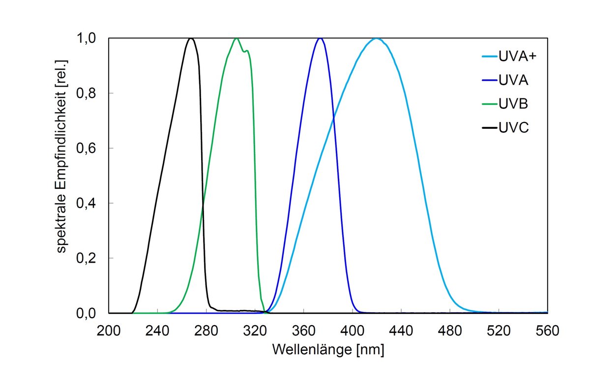
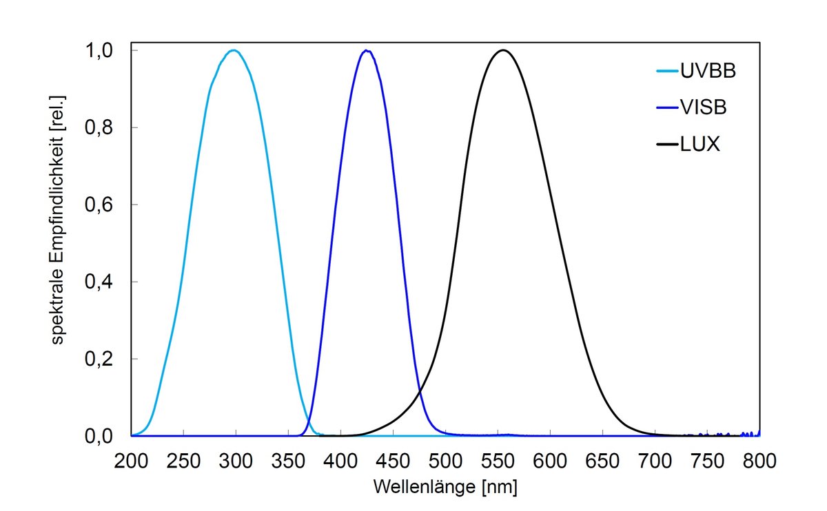
View the UVx-SE as a 3D model
Look at the pressure-resistant sensor from every side, rotate and zoom – directly in your browser.
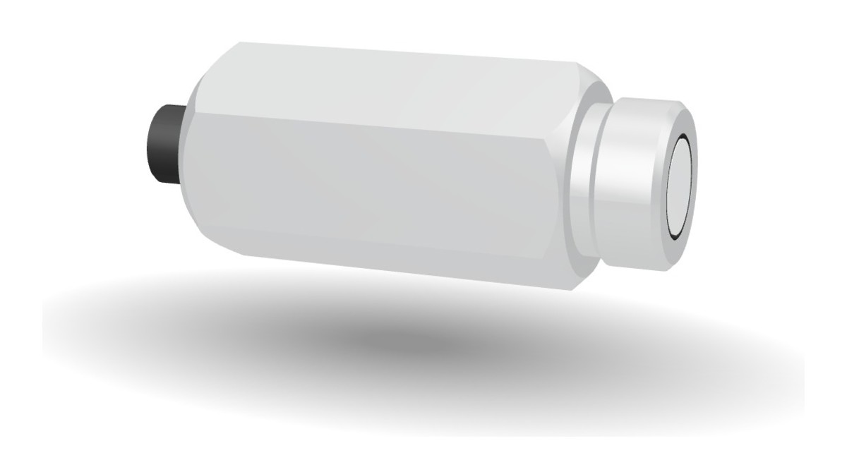
The UVx-SE can be viewed from all sides in the 3D product viewer – true to the original, generated from the CAD design data. For planning the installation in reactors and pipes, the spatial view shows housing shape, window and connector at a glance.
Technical data water proof UV-sensor UVx-SE
| Measuring range | 0 - 200 mW/cm² |
| Measuring range option | 0 - 20 mW/cm² |
| Connector | G 3/4“ |
| Dimensions | see drawing |
| Housing material | stainless steel |
| Weight | ~420 g |
| Water pressure | up to 10 bar |
| Operating voltage | 24 V |
| Operating current | <15 mA |
| Output | 0 - 10 V or 4 - 20 mA |
| Operating temperature | 0 to 60 °C |
| Storage temperature | -10 to 60 °C |
| Humidity | < 80%, non-condensing |
| Cable | 2 m – 10 m |
| Sensor connector | M12 (5-pole) |
Connection and pin assignment
| Name | Wire colour | Connector PIN |
|---|---|---|
| GND / Shield | brown | PIN 1 |
| Supply 24 VDC | white | PIN 2 |
| not used | – | PIN 3 |
| Signal High 0 – 10 VDC | black | PIN 4 |
| Signal Low | grey | PIN 5 |
On versions with an open cable end there is no connector; the wire colours remain the same.
| Name | Wire colour | Connector PIN |
|---|---|---|
| Supply 24 VDC | brown | PIN 1 |
| Supply 24 VDC | white | PIN 2 |
| GND / Shield | blue | PIN 3 |
| GND / Shield | black | PIN 4 |
| not used | – | PIN 5 |
The sensor sits in the current loop: PIN 1 and PIN 2 carry the supply, PIN 3 and PIN 4 the return. The measuring instrument or PLC input is placed in the return line and reads the loop current. On versions with an open cable end there is no connector; the wire colours remain the same.
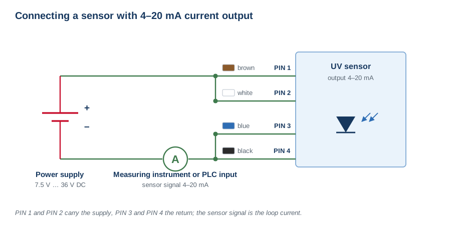
Connection in the current loop, supply 7.5 V to 36 V DC.
The connecting cables are available with an M12 female or an M12 male connector. Both diagrams show the mating face, so the contacts are mirrored with respect to each other. The keyway fixes the orientation.
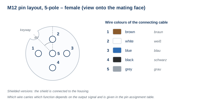
M12 female connector, 5-pole – view onto the mating face.
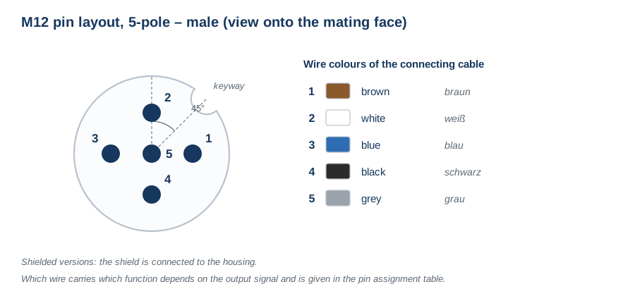
M12 male connector, 5-pole – view onto the mating face.