

PLC UV sensors & VIS sensors
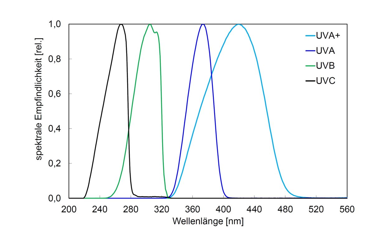
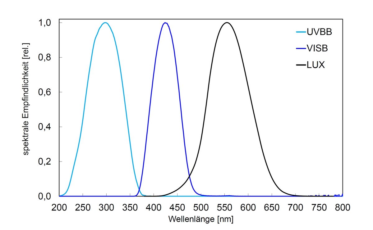
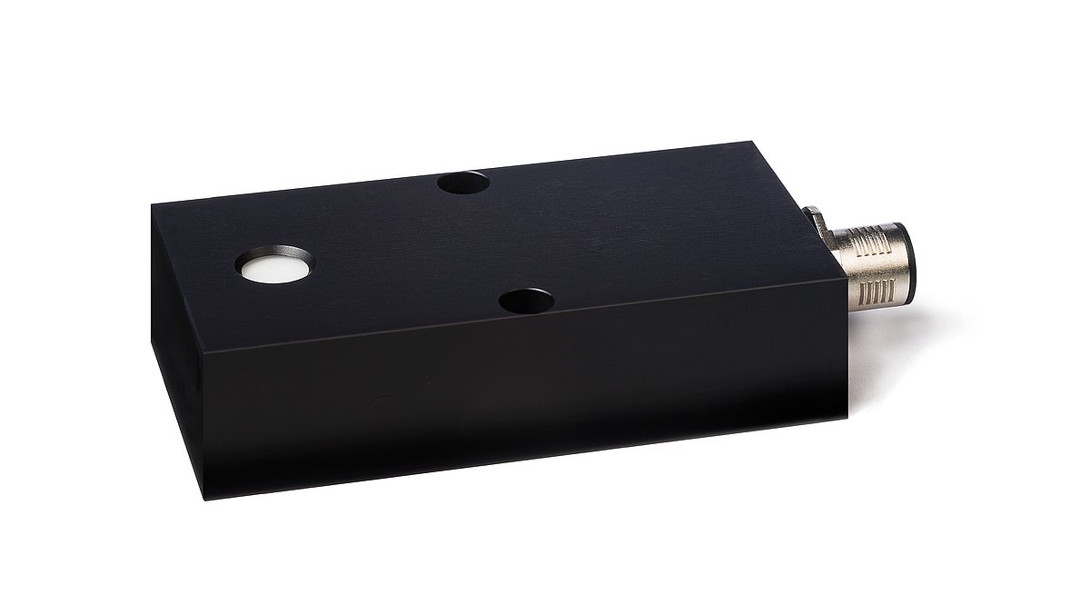
The PLC UV sensors and VIS sensors serve as precision sensors for the measurement of UV irradiances and illuminances in systems with programmable logic controllers (PLCs). Available are spectral ranges from UVC (200–280 nm) to VIS (380–780 nm), three measuring ranges from 0–100 mW/cm² to 0–5000 mW/cm² and the output signals 4–20 mA, 0–10 V or 0–2 V. The built-in diffusers provide the required cosine correction.
The integrated electronics generate a signal voltage that is transmitted with the low interference cable to the PLC. The sensors are calibrated with traceability to the PTB (Physikalisch Technische Bundesanstalt, the German national test authority); after being calibrated, they are shipped with a factory calibration certificate.
Excellent long-term stability is achieved through the use of appropriate materials. Of course, a repair and spare parts service is available for many years. For special applications, the sensors are available and with customer-specific measurement and spectral ranges.
For small control tasks, the PLC sensors can be connected to an RM-32 panel meter. The RM-32 shows the current irradiance on a 3.5-digit digital display and switches two relay contacts with adjustable warning and alarm signals.
To protect the sensor against contamination and aging (at extremely high irradiance and periodic reference measurements) we recommend our shutter.
Applications of PLC UV sensors and VIS sensors
- Sensors in PLC systems
- Control of UV LEDs and spotlights
- Precise measurement of irradiance and illuminance
Highlights of PLC UV sensors and VIS sensors
- Direct PLC operation
- Selectable signal output
- Long-term stability
- Recalibratable sensors
- Integrated electronics
- Selectable measurement ranges
- Shutter optional
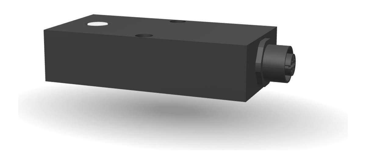
View the PLC sensor as a 3D model
Look at the sensor housing and its connectors from every side – directly in your browser.
The PLC sensor with analogue output signal can be viewed from all sides in the 3D product viewer – true to the original, generated from the CAD design data. Housing shape, connector and mounting dimensions can thus be examined in detail before planning.
Specifications of PLC UV sensors and VIS sensors
| Measuring range | 0 - 100 mW/cm² |
| 0 - 200 mW/cm² | |
| 0 - 5000 mW/cm² | |
| Power supply | 24 V, 12 V, 5 V or ±5 V |
| Current input | < 15 mA |
| Signal output | 4 – 20 mA, 0 - 10 V, 0 - 2 V |
| Operation temp. | 0 to 60 °C |
| Storage temp. | -10 to 60 °C |
| Humidity | < 80% Non-condensing |
| Connector | 5-pole M12 |
| Dimensions | 80 x 40 x 20 mm |
| Weight | 150g |
Connection and pin assignment
| Name | Wire colour | Connector PIN |
|---|---|---|
| GND / Shield | brown | PIN 1 |
| Supply 24 VDC | white | PIN 2 |
| not used | – | PIN 3 |
| Signal High 0 – 10 VDC | black | PIN 4 |
| Signal Low | grey | PIN 5 |
On versions with an open cable end there is no connector; the wire colours remain the same.
| Name | Wire colour | Connector PIN |
|---|---|---|
| GND / Shield | brown | PIN 1 |
| Supply 12 VDC | white | PIN 2 |
| not used | – | PIN 3 |
| Signal High 0 – 10 VDC | black | PIN 4 |
| Signal Low | grey | PIN 5 |
On versions with an open cable end there is no connector; the wire colours remain the same.
| Name | Wire colour | Connector PIN |
|---|---|---|
| Supply 24 VDC | brown | PIN 1 |
| Supply 24 VDC | white | PIN 2 |
| GND / Shield | blue | PIN 3 |
| GND / Shield | black | PIN 4 |
| not used | – | PIN 5 |
The sensor sits in the current loop: PIN 1 and PIN 2 carry the supply, PIN 3 and PIN 4 the return. The measuring instrument or PLC input is placed in the return line and reads the loop current. On versions with an open cable end there is no connector; the wire colours remain the same.
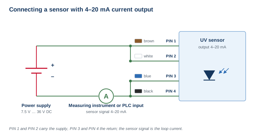
Connection in the current loop, supply 7.5 V to 36 V DC.
The connecting cables are available with an M12 female or an M12 male connector. Both diagrams show the mating face, so the contacts are mirrored with respect to each other. The keyway fixes the orientation.
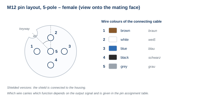
M12 female connector, 5-pole – view onto the mating face.
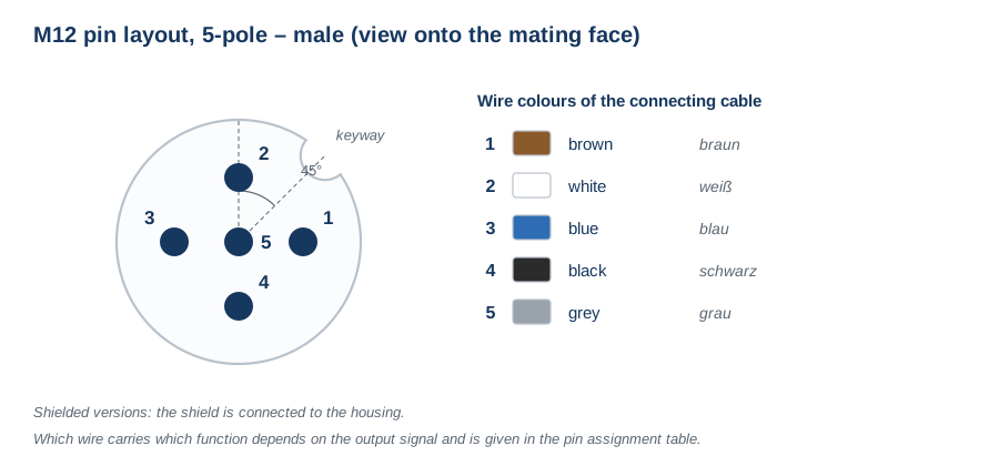
M12 male connector, 5-pole – view onto the mating face.
Frequently asked questions on PLC sensors
4–20 mA, 0–10 V or RS-485 for UV sensors?
0–10 V is the simplest solution for short runs inside the cabinet, but it reacts sensitively to cable length, voltage drop and interference. 4–20 mA is the industrial standard for long distances and noisy environments: the current stays constant over the cable length, and the live zero at 4 mA makes a broken wire distinguishable from a reading of zero. RS-485 and other digital interfaces transmit the value without D/A conversion, allow several sensors on one bus and carry status, serial number and calibration data along with the reading. For new connections with diagnostic requirements, digital is the first choice; 4–20 mA remains the most robust analogue compromise.
Which spectral and measuring ranges are available for PLC sensors?
Seven spectral ranges: UVC 200–280 nm, UVB 280–315 nm, UVA 315–400 nm, UVA+ 330–455 nm, UVBB 230–400 nm, VISB 400–480 nm and VIS 380–780 nm with V(λ) weighting. Plus three measuring ranges: 0–100 mW/cm², 0–200 mW/cm² and 0–5000 mW/cm². Output signal, supply voltage and measuring range are chosen to suit the measuring task and the controller; customer-specific measuring and spectral ranges as well as special housings are possible.
How is a limit value monitored without a PLC?
With the RM-32 panel instrument, to which the PLC sensor is connected directly. It shows the current irradiance on a 3½-digit display and outputs adjustable warning and alarm signals via two relay contacts. For small control tasks that replaces the connection to a programmable logic controller entirely.
How is the sensor protected against contamination and ageing?
With an electronic shutter that exposes the sensor only for the measurement. This is advisable for periodic reference measurements and especially at extremely high irradiance, because both contamination and sensor ageing progress faster there. In general the sensors are calibrated traceably to the PTB, can be recalibrated, and are long-term stable through the choice of materials.