

Inline UV sensors: continuous irradiance measurement for UV systems
The inline UV sensor FLT measures UV irradiance continuously in running UV systems and makes declining lamp output visible before scrap is produced. Measuring 68 × 25 × 15 mm, it covers seven spectral ranges and four measuring ranges up to 0–20 W/cm² and can be connected either directly to a PLC or to the RMD and RM-12 radiometers. Because inline and hand-held measurement use the same sensor design, comparison and reference measurements need no conversion; all sensors are calibrated traceably to the PTB.
Typical installations are:
- packaging systems
- disinfection systems
- systems for surface activation
- UV curing systems
- Aging & test chambers
The system consists of a compact inline sensor for fixed installation or use with the RMD/RM-12 radiometers. Reference measurements are simple and precise due to identical shape of both sensor versions.
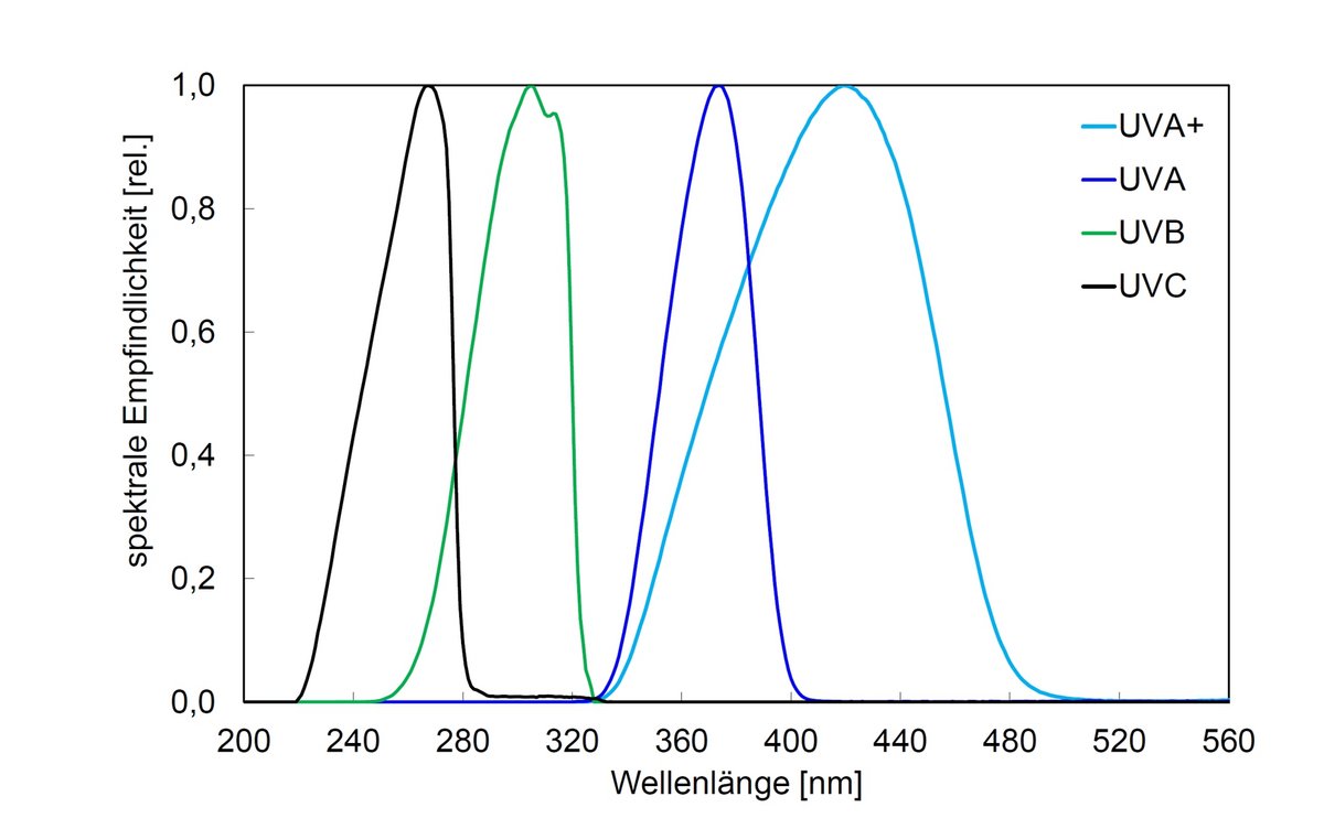
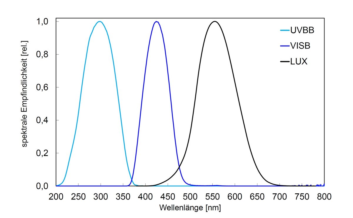
Our product range includes seven spectral ranges and four measuring ranges for the sensors. This allows the radiometric sensors to be optimally adapted for the application. The sensors are calibrated with traceability to PTB (Physikalisch Technische Bundesanstalt, the German national test authority); after being calibrated, they are supplied with a factory calibration certificate.
The RMD is characterized by a very high resolution, a high measuring range, a data interface and the illuminated graphic display.
For small control tasks, the inline sensor FLT can be connected to a panel meter, like RM-32. The RM-32 shows the current irradiance on a 3.5-digit digital display and offers potential-free relay contacts with adjustable switching thresholds for warning and alarm signals.
Applications of inline UV sensors
- UV and illumination sensors for PLC
- Inline and reference measurements
- Precise measurement of irradiance

Highlights of UV inline sensors
- Direct PLC operation
- Reduced height
- Long-term stability
- Seven spectral ranges
- Four measurement ranges
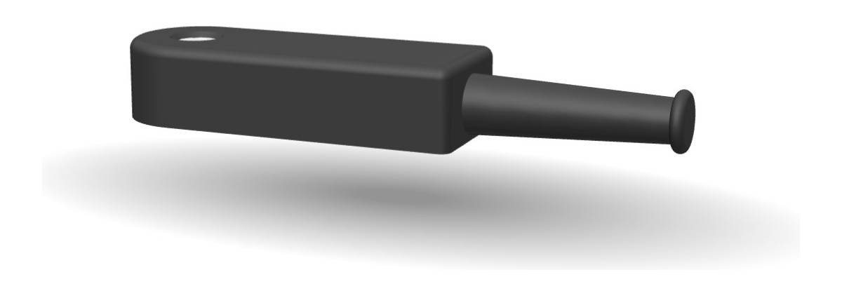
View the FLT inline sensor as a 3D model
Look at the flat sensor head from every side, rotate and zoom – directly in your browser.
The FLT inline sensor can be viewed from all sides in the 3D product viewer – true to the original, generated from the CAD design data. Especially for the question whether the flat design fits into the process, the spatial view helps more than a dimensional drawing.
Connection and wire colours
The FLT inline sensor for PLC operation is supplied with a cable without a connector, so there is no pin assignment. Sensors from 2025 onwards use wire colours V2, earlier ones wire colours V1.
| Name | Wire colour V1 (until 2025) | Wire colour V2 |
|---|---|---|
| GND / Shield, 0 VDC | blue | brown |
| Supply 24 VDC | red | white |
| Signal High | yellow | black |
| Signal Low | green | grey |