

UV Fluorescent Penetrant Testing and Industrial Inspection
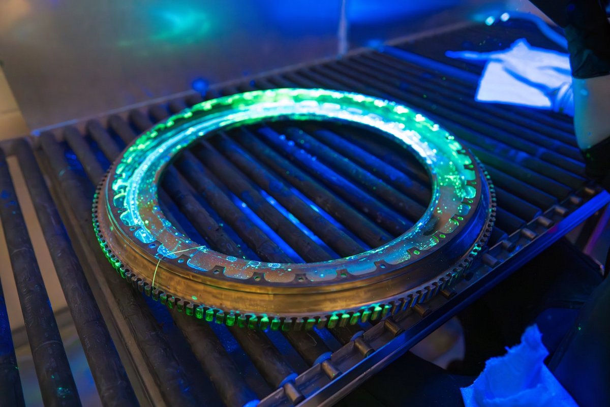
In fluorescent penetrant testing, the final judgment is made by an eye or a camera. Both are sensitive, but neither is calibrated: they assess contrast, not absolute values. Reproducibility therefore does not come from a brighter lamp, but from fixed boundary conditions – excitation wavelength, irradiance at the part, uniformity of the field, and ambient light. Fluorescent penetrant testing is the classic visual method of non-destructive testing (NDT): a fluorescent penetrant or magnetic particle medium makes cracks, porosity and other surface-breaking defects visible under UV-A excitation that would remain invisible in daylight. The central physical quantities are the spectral excitation of the fluorophore, the irradiance at the inspection point, residual visible light, and the inspector's dark adaptation.
How is the market for non-destructive fluorescent inspection developing?
No statistically well-defined market exists for “fluorescent penetrant testing” on its own; a more reliable reference is the broader non-destructive testing (NDT) market and its liquid penetrant testing segment. The global NDT market was valued at USD 22.86 billion in 2025 and is projected to reach USD 33.78 billion by 2031, growing at 6.72 % CAGR between 2026 and 2031 (Mordor Intelligence, 2026). A narrower indicator is the liquid penetrant testing market, estimated to reach USD 1.84 billion by 2030; fluorescent systems held a 61.4 % share of that market in 2024 and are growing at roughly 6.2 % per year, faster than visible-dye methods (Mordor Intelligence, 2026).
This growth is not automatic; it shifts requirements on process and measurement. Maintaining ageing aircraft fleets calls for tightly repeatable penetrant inspections under aerospace specifications such as SAE AMS2647, making documentation of irradiance and uniformity mandatory. Serial inspection of die-cast aluminium parts – such as battery housings for electric vehicles – increases the share of automated, camera-based fluorescent inspection stations; automated and robotic inspection cells already reached a 15 % revenue share of the liquid penetrant testing market in 2024, with a forecast growth rate of 9.7 %. And the shift from mercury-vapour lamps to UV-LED sources is fundamentally changing the photometric boundary conditions of the test – the reason ASTM E3022 exists as its own standard.
This shift is the most defining technological change in the field; it alters not only electrical efficiency but also spatial field characteristics, making denser field mapping necessary because the LED field falls off more steeply than that of a gas-discharge lamp. A second driver is the miniaturisation of portable inspection sources for field maintenance work, coupled with the need to measure the discharge curve of battery-powered lamps.
Third, assessment itself is shifting from purely visual inspection towards automated, camera-based inspection with learning-based image analysis, which makes triggerable, reproducible illumination a basic requirement rather than a convenience. Fourth, the environmental footprint of penetrant materials themselves is drawing more attention: sensitivity, cost and environmental compatibility are increasingly evaluated together, rather than maximising sensitivity alone (see Scientific literature below). Fifth, aerospace-specific in-house specifications such as SAE AMS2647 tighten minimum requirements for UV sources beyond the general ISO and ASTM values in places, forcing suppliers to update their inspection equipment.
How does fluorescent excitation work?
A fluorophore absorbs photons within an excitation band and re-emits part of that energy at longer wavelengths. Between the two lies an unavoidable loss – the visible emission is always weaker than the excitation, because part of the absorbed energy is released as heat through non-radiative relaxation before the molecule emits a photon. What matters is spectral overlap: radiation outside the excitation band contributes nothing to fluorescence, however much power stands behind it.
For common industrial penetrants, the excitation band sits around 365 nanometres, which is why this wavelength is the default for lamps and LEDs; ASTM E3022 gives a typical range of 347 to 382 nanometres for LED sources (Magnaflux, 2024). For other markers – leak-test tracers, process dyes, fluorescent coatings – the excitation band can differ; the penetrant's data sheet then determines the appropriate source, not the other way round. A second requirement concerns what the source should not emit: residual visible light raises the background and reduces contrast, and short-wavelength components below the excitation band expose the inspector without any measurement benefit.
Which technologies are used for UV-A excitation?
Several light sources are available to excite fluorescent penetrants, differing markedly in spectrum, beam characteristics and ageing behaviour. Traditional mercury-vapour lamps produce a broad, soft irradiance field but need a warm-up time of up to ten minutes and a UV-A band-pass filter to exclude visible and shorter-wavelength light (mr-chemie, 2025). UV-LED sources are ready instantly, more electrically efficient and spectrally more stable, but deliver a narrower field with a steeper edge falloff and age through a different mechanism than gas-discharge lamps. Xenon and other high-intensity discharge lamps are used where very high irradiance is needed briefly, such as flash illumination for automated camera systems.
| Technology | Characteristics | Advantages | Limitations | Typical use |
|---|---|---|---|---|
| Mercury-vapour lamp (medium pressure) | broad, soft irradiance field; line spectrum around 365 nm plus visible side lines | large-area, uniform illumination; established normative basis (ASTM E2297) | warm-up time up to 10 min; contains mercury; requires a UV-A band-pass filter; ages with operating hours | stationary inspection booths, large inspection areas |
| UV-A LED | narrow-band spectrum around 365 nm; steep field edge falloff | instant-on; low heat output; triggerable for camera synchronisation; no mercury | narrow beam field requires denser field mapping; needs its own test standard (ASTM E3022) | hand lamps, spot sources, automated inspection cells |
| Xenon/HID flash lamp | very high momentary irradiance; broadband spectrum | high peak power for camera-based inline inspection | needs additional filtering; higher thermal and electrical complexity | automated image processing on the camera cycle |
| Medium-pressure hand lamp | portable, mains- or battery-powered | works on hard-to-reach parts and in the field (MRO) | irradiance falls with the square of distance; depends on battery state | maintenance, on-site inspection of aircraft and plant |
What standards set the framework?
For the classic methods, this framework is set out normatively. ASTM E1417/E1417M describes how the penetrant test is carried out, including dwell, intermediate-cleaning and development times; ASTM E2297 covers traditional UV-A and white-light sources and the meters used to test them, defining the UV-A range as 320 to 400 nanometres and the visible range as 400 to 760 nanometres (Magnaflux, 2024). ASTM E3022 adds its own requirements and measurement procedures for LED-based UV-A lamps used in penetrant and magnetic-particle testing. Internationally, the ISO 3452 series governs penetrant materials, classifying fluorescent penetrants as Type I, visible-dye penetrants as Type II and dual-purpose penetrants as Type III, in five sensitivity levels from "very low" to "ultra-high" (ISO 3452-2:2021). Viewing conditions themselves are governed by ISO 3059: it requires at least 1,000 µW/cm² (10 W/m²) of UV-A irradiance at the inspection point, recommends an upper guideline of 5,000 µW/cm² (50 W/m²), and caps visible ambient light at 20 lux (ndtmachine.com, 2025). In aerospace, manufacturer-specific specifications such as SAE AMS2647 add their own, sometimes stricter, minimum values for irradiance and inspection intervals. An overview of UV spectral ranges and their normative limits in general is given on the page Guidelines, Standards and Norms in UV.
The shift from gas-discharge lamps to LEDs is exactly why ASTM E3022 exists as a separate document. LEDs bring a more stable spectrum and less heat, but a different beam pattern: narrower fields with a steeper edge falloff, where the traditional lamp had a broad, soft distribution. A procedure written for one lamp type therefore does not carry over to the other without re-measurement.
Which process variables are decisive?
Four quantities determine whether a fluorescent indication is reliably found, and none can substitute for another. UV-A irradiance at the part (not at the lamp) determines how many excitation-band photons actually reach the fluorophore – it falls with the square of the working distance and must therefore be measured at the actual inspection point, not at the lamp housing. Uniformity of the irradiance field determines whether the same sensitivity applies across the whole inspection area; a non-uniform field produces position-dependent results that change with where the part happens to be placed.
Residual visible light, from the source itself and from the inspection environment, sets the background against which the weak fluorescence must be detected; because human perception judges contrast rather than absolute luminance, every additional lumen lowers the effective detection limit. Dark adaptation of the inspector, finally, is a biological rather than a physical process variable, but is just as firmly anchored in the norms: most procedures require a minimum adaptation time of one minute before inspection, since eye sensitivity to weak light only rises sufficiently after that time.
What limits the process or causes errors?
The most common misconception concerns electrical lamp power: a wattage figure describes power consumption, not the optical power radiated within the excitation band, and certainly not the irradiance that reaches the part. Two lamps of equal electrical power can produce very different irradiance at the component because of differing efficiency, optics and ageing state. A second common misconception is that an irradiance once measured as "sufficient" stays valid indefinitely: UV lamps and UV LEDs age at different rates, LED chips primarily through semiconductor degradation and partly through cracking of the encapsulant; without recurring control measurements this decline goes unnoticed until the inspection is effectively running below its released sensitivity.
Third, the measurement position is often chosen poorly: a check measurement at the lamp housing or in the centre of the image says little about how the field looks at the edges of the actual inspection area or on a curved part geometry. Especially with UV LEDs and their steep edge falloff, an irradiance that is compliant at the centre can already fall well below the required minimum at the edge of the inspection area. Fourth, a time figure alone – a fixed inspection duration – is no substitute for a dose figure: as long as the irradiance at the inspection point is unknown, it remains unclear what actual excitation occurred during that time. The same logic – dose instead of time – applies in a related field with a different target quantity, UV Ageing, Colour Fastness and Photostability; for the visual assessment used in fluorescent penetrant testing, time-dose reciprocity does not hold in the same way it does for integrating sensors.
How do part geometry, surface and material matter?
Surface roughness and porosity affect the test result independently of excitation and irradiance. Additively manufactured parts with typical powder-bed surface roughness present a fundamental limit for classic penetrant testing: without post-processing or polishing it is unsuitable for porous or rough additively manufactured structures, because penetrant collects in surface pores rather than genuine cracks and remains there after the wash step. For dense, non-porous additively manufactured structures, the method remains applicable.
Even on conventionally manufactured parts, geometry affects the irradiance field: concave radii, bores and undercuts create shadowing that a flat reference sample does not show, and should therefore be estimated in advance – for example using optical simulation – before a test procedure is fixed for a complex part.
Photon energy and Stokes shift as the efficiency limit of fluorescence
The maximum detection sensitivity of a fluorescent indication is physically limited, not only by the penetrant used. By conservation of energy, an emitted photon can never carry more energy than the absorbed excitation photon; photon energy is given by
E = h · c / λ
where h is the Planck constant, c the speed of light and λ the wavelength.
Because the emission wavelength of fluorescent penetrants is always longer than the excitation wavelength (Stokes shift), every emitted photon carries less energy than the absorbed one – the remainder is released as heat through non-radiative relaxation in the molecule, an effect described by Kasha's rule. In addition, no fluorophore re-emits every absorbed photon; the ratio of emitted to absorbed photons is the quantum yield (Φ) and is typically well below one for practical penetrants.
Practical consequence: even an ideally matched, loss-free excitation source cannot raise visible fluorescence intensity above the maximum set by the Stokes shift and the quantum yield. Increasing irradiance therefore only improves the signal as long as the penetrant is not driven into saturation or self-absorption; beyond that point, only the inspector's unnecessary exposure increases, not the contrast of the indication.
Worked example: how much excitation energy is lost as heat?
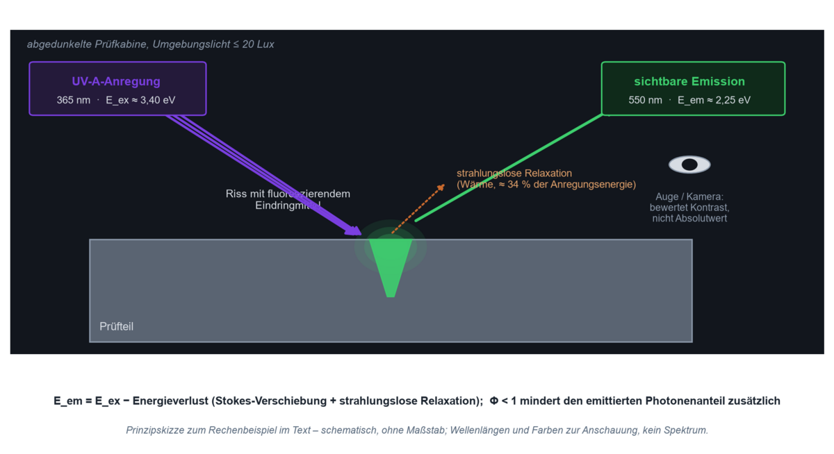
Assumptions: excitation wavelength λ_ex = 365 nm (the default for industrial UV-A sources), emission maximum of a typical yellow-green fluorescent penetrant λ_em ≈ 550 nm.
Formula: E = h · c / λ, using h · c ≈ 1240 eV·nm as a practical approximation.
Calculation: E_ex = 1240 / 365 ≈ 3.40 eV; E_em = 1240 / 550 ≈ 2.25 eV.
Result: the relative energy loss per emitted photon is (3.40 − 2.25) / 3.40 ≈ 34 percent.
Practical interpretation: the Stokes shift alone already turns roughly a third of the excitation energy into heat inside the molecule, before the quantum yield Φ < 1 further reduces the usable photon fraction. Together, these two effects explain why fluorescent indications are inherently low-light and why ambient and stray light have a disproportionately large effect on detectability – the limiting factor is not excitation power, but the low optical yield of the conversion process itself.
Where is UV fluorescent penetrant testing used?
In aerospace, fluorescent penetrant and magnetic-particle testing is a fixed part of manufacturing and maintenance release for turbine blades, landing-gear parts and safety-critical castings; the critical requirement is unbroken documentation of irradiance and calibration status under specifications such as SAE AMS2647, since inspections are audited. In the automotive and supplier industry, automated fluorescent inspection tunnels check die-cast aluminium parts – such as engine blocks or battery housings for electric vehicles – for porosity and cracks at production rate; here, reproducibility of irradiance across high volumes and changing part positions is the critical process variable.
In power generation, turbine components, pressure vessels and pipeline welds are inspected, often in the field with portable UV hand lamps, where distance and ambient light are harder to control than in a stationary booth. In additive manufacturing, fluorescent penetrant testing complements post-processing of dense, non-porous parts, while porous structures require additional or alternative inspection methods. In medical technology this includes titanium cast implants, where surface defects are directly safety-relevant.
Which UV source suits large areas, bores, field use and machine vision?
For large-area, stationary inspection, area emitters or arrangements from the Series L are suitable, producing as uniform a field as possible across the whole inspection area. For hard-to-reach geometries – bores, undercuts, internal contours – compact UV LED spot sources or endoscope/borescope attachments are used, directing their narrow field precisely at the critical location.
For mobile field inspection, for example in aircraft or plant maintenance, battery-powered UV hand lamps are common; here the discharge curve of irradiance over operating time must be taken into account, since ASTM E3022 specifies either a discharge curve or the time to fall below 1,000 µW/cm² as a test quantity for battery-powered LED lamps. For ferromagnetic parts, fluorescent magnetic-particle testing replaces penetrant testing; it uses the same photometric boundary conditions but is governed by its own standards (ASTM E1444, ASTM E3024). For automated image processing, triggerable UV-LED sources are used, with flash duration and intensity synchronised to the camera frame.
Which quantities must be measured or monitored?
The starting point of any measurement task is not a device, but the question of which quantity the test standard actually requires. For classic, visually assessed penetrant and magnetic-particle testing, this is primarily UV-A irradiance at the inspection point in µW/cm² or W/m², measured with a radiometer such as the RMD Pro, whose spectral response is limited to the UV-A range. A broadband measurement is sufficient as long as the source has a known, standard-compliant spectrum; but once sources with markedly different spectral distributions are compared – an older mercury-vapour lamp against a new UV LED, for instance – spectral measurement becomes necessary, as provided by the UVpad. A broadband sensor can deviate systematically at a narrow-band source; this effect is called spectral mismatch and is one of the most commonly underestimated sources of measurement error in this field.
Beyond irradiance, residual visible light from the source and ambient light in the booth must also be captured, since ISO 3059 defines its own limit for this. Spatial measurements – mapping irradiance across several points of the inspection field – become necessary whenever the inspection area is larger than the uniform centre of the beam profile, or when part geometry can cause shadowing. Time-resolved measurements – recurring checks rather than a one-off acceptance test – are needed because both gas-discharge lamps and LEDs lose radiant power over their operating life.
The workplace itself is the second measurement task: staff at fluorescent inspection stations spend extended periods near a UV-A source. Which quantities matter from an occupational-safety perspective is described in UV Erythema in the Workplace.
Once a camera takes over the assessment, lighting requirements become stricter, because an image-processing algorithm compares grey values against a fixed threshold; if illumination varies between parts, or drifts over the source's operating life, that threshold drifts with it and the defect-detection rate changes unnoticed. Triggerable UV LEDs can be synchronised with a camera, robot or conveyor and deliver the same defined excitation in every frame – that is the real advantage over a continuously burning lamp, not merely higher light output.
Recent developments combine this controlled illumination with learning-based image analysis: a system published in 2026 for automated fluorescent inspection of turbine blades uses an adapted YOLOv8 architecture to classify cracks, cold shuts, inclusions and porosity, reaching an average detection accuracy of 93.3 percent (see Scientific literature below). For process documentation – especially in audited industries such as aerospace – continuous logging of irradiance and calibration status belongs in the inspection record as a data set, not just as a one-off acceptance value.
What does the scientific literature show?
Four papers provide the technical basis for the central claims made in this text about LED ageing, inspection limits in additive manufacturing, penetrant selection and automated image analysis:
- Ageing of UV-A LEDs. A study of the ageing of commercial 3-watt UV-A LEDs (365 nm) under continuous and cyclic operation shows that cyclic operation extends lifetime considerably compared with continuous operation, and that optical power degradation is caused primarily by semiconductor ageing and secondarily by cracking of the encapsulant – a finding directly relevant to maintenance intervals for UV-LED inspection lamps. – Arques-Orobon, F. J.; Vazquez, M.; Nuñez, N. (2020): Lifetime Analysis of Commercial 3 W UV-A LED, Crystals 10(12), 1083.
- Limits of penetrant testing in additive manufacturing. A review of defect-inspection technologies for additive manufacturing classifies penetrant testing as sensitive but unsuitable, without prior polishing, for porous or rough additively manufactured surfaces, thereby delimiting its scope against dense, conventionally manufactured parts. – Chen, Y.; Peng, X.; Kong, L. B.; Dong, G. X.; Remani, A.; Leach, R. (2021): Defect inspection technologies for additive manufacturing, International Journal of Extreme Manufacturing 3(2).
- Penetrant selection under sustainability criteria. A study on selecting fluorescent penetrants develops an evaluation model that includes environmental and safety criteria alongside sensitivity and cost, illustrating an evaluation approach that goes beyond raw test sensitivity. – Pacana, A.; Siwiec, D.; Bednárová, L. (2020): Method of Choice: A Fluorescent Penetrant Taking into Sustainability Criteria, Sustainability 12(14), 5854.
- Automated, AI-assisted fluorescent inspection. A paper published in 2026 describes an automated, AI-assisted fluorescent inspection system for turbine blades based on an adapted YOLOv8 architecture, classifying four typical surface defect types with an average detection accuracy of 93.3 percent, illustrating the trend towards automated image analysis under controlled illumination. – Wu, D.; Deng, D.; Li, H.; Wang, H.; Zhao, B. (2026): Fluorescent penetrant inspection system for minor defects in jet-engine blade surface, Journal of Intelligent Manufacturing 37(8), 3105–3121.
Technical background and further reading
Four further sources on standards, occupational safety and market data underlying this text:
- Standards for penetrant and magnetic-particle testing. ASTM E1417/E1417M (procedure), E2297 (traditional UV-A and white-light sources and meters), E3022 (LED-based UV-A lamps) and E1444/E3024 (magnetic-particle testing). Overview: ASTM E3022 – BSI Group.
- ISO/DIN EN ISO penetrant testing. ISO 3452-1/-2 (fundamentals and penetrant material testing) and ISO 3059 (viewing conditions for penetrant and magnetic-particle testing). Source: ISO 3452-2:2021.
- Occupational safety around UV-A test sources. ICNIRP guidance on protecting workers from UV radiation, including the classification of "black light" sources used in non-destructive testing (ICNIRP – Protecting Workers from Ultraviolet Radiation); in Germany, supplemented by the ordinance on artificial optical radiation (OStrV), Gesetze im Internet.
- Market data. Mordor Intelligence, "Non-Destructive Testing (NDT) Market" and "Liquid Penetrant Testing (PT) Market", 2026.
FAQ on UV fluorescent penetrant testing
How does fluorescent excitation work in penetrant testing?
A fluorescent penetrant remaining in a crack or pore absorbs UV-A radiation around 365 nanometres and re-emits part of that energy as visible light at a longer wavelength. Because this emission is always weaker than the excitation, a dark, low-contrast background is just as important for detectability as excitation intensity itself.
Which wavelength is suitable for industrial fluorescent penetrant testing?
For the great majority of industrial penetrant and magnetic-particle materials, the excitation maximum sits around 365 nanometres, which is why UV-A lamps and LEDs in this range are the default. For other markers such as leak-test tracers or specialty coatings, the optimal excitation band can differ; the penetrant's data sheet is always the authority.
What UV-A irradiance is required for a compliant inspection?
ISO 3059 requires at least 1,000 µW/cm² (10 W/m²) of UV-A irradiance at the inspection point, with a recommended upper guideline of around 5,000 µW/cm² (50 W/m²). Aerospace-specific specifications such as SAE AMS2647 may prescribe different, sometimes higher, minimum values, so the applicable customer specification always takes precedence.
What is the difference between mercury-vapour lamps and UV-LED inspection lamps?
Mercury-vapour lamps deliver a broad, soft irradiance field but need a warm-up time of up to ten minutes and a UV-A band-pass filter. UV LEDs are ready instantly and more electrically efficient, but produce a narrower field with a steeper edge falloff, which is why they must be tested and mapped separately under the dedicated standard ASTM E3022.
Why does a fluorescent inspection fail to perform reliably despite nominally sufficient lamp power?
A lamp's electrical power consumption does not describe the optical power radiated within the excitation band, let alone the irradiance reaching the part. Ageing, distance, filter condition and part geometry change this value independently of rated power, which is why only a measurement at the actual inspection point is reliable. The underlying definitions and units are listed in the overview of radiometric quantities.
How is irradiance measured in fluorescent penetrant testing?
Measurement uses a UV-A radiometer whose spectral response is limited to the 320-to-400-nanometre range, taken directly at the inspection point and at the actual working distance. When source spectra differ markedly, a spectral measurement is also advisable to rule out spectral mismatch in the sensor.
What factors limit fluorescent penetrant testing on additively manufactured parts?
The typical surface roughness and porosity of powder-bed additive manufacturing causes penetrant to collect in surface pores rather than genuine cracks and remain there. Without post-processing or polishing, classic penetrant testing is therefore only of limited value on such surfaces; for dense, smooth additively manufactured structures it remains applicable.
How is fluorescent penetrant testing monitored in automated plants?
Triggerable UV-LED sources are synchronised with a camera, robot or conveyor so that every part receives the same defined excitation, while an image-processing algorithm assesses fluorescence intensity against a fixed threshold. Irradiance and calibration status of the source are additionally logged continuously and kept as part of the auditable process record.
Related application fields
Fluorescent inspection touches on three further fields: in aerospace the same penetrant inspection is governed by dedicated company standards and qualification requirements, occupational safety assesses the UV-A exposure of inspection staff at the booth, and automation and process integration describes the triggerable, reproducible illumination that camera-based evaluation depends on. The same inspection means appear in additive manufacturing and in optics and precision components; the Markets & Applications overview places all fields in context.
Autor: Dr. Mark Paravia
Dr.-Ing. Mark Paravia ist Geschäftsführer der Opsytec Dr. Gröbel GmbH in Ettlingen und leitet das akkreditierte Kalibrierlabor. Nach seiner Forschung zu gepulsten Xenon-Excimer-Entladungen am Lichttechnischen Institut des KIT gilt sein Schwerpunkt heute der optischen Strahlungsmesstechnik. Er ist anerkannter UV-Experte, stellvertretender Obmann im DIN-Normungsausschuss FNL 7 „Optische Strahlung" und Mitglied im DVGW-Projektkreis UV-Desinfektion.
Advice on fluorescent penetrant testing
Unsure what irradiance and uniformity actually reach the inspection surface – or whether your current UV source still meets the standard there? A measurement at the real inspection point provides clarity before a finding becomes disputed – send us your question.